Next: 8.4.3 Optimal Navigation Functions Up: 8.4 Complete Methods for Previous: 8.4.1.2 Navigation functions
This section describes how to construct a piecewise-smooth vector field over a cell complex. Only normalized vector fields will be considered. It is assumed that each cell in the complex has a simple shape over which it is easy to define a patch of the vector field. In many cases, the cell decomposition techniques that were introduced in Chapter 6 for motion planning can be applied to construct a feedback plan.
Suppose that an ![]() -dimensional state space
-dimensional state space ![]() has been decomposed
into a cell complex, such as a simplicial complex or singular complex,
as defined in Section 6.3.1. Assume that the goal set
is a single point,
has been decomposed
into a cell complex, such as a simplicial complex or singular complex,
as defined in Section 6.3.1. Assume that the goal set
is a single point, ![]() . Defining a feedback plan
. Defining a feedback plan ![]() over
over
![]() requires placing a vector field on
requires placing a vector field on ![]() for which all integral
curves lead to
for which all integral
curves lead to ![]() (if
(if ![]() is reachable). This is
accomplished by defining a smooth vector field for each
is reachable). This is
accomplished by defining a smooth vector field for each ![]() -cell.
Each
-cell.
Each ![]() -cell is a switching boundary, as considered in Section
8.3.1. This leads directly to solution trajectories in
the sense of Filipov. If
-cell is a switching boundary, as considered in Section
8.3.1. This leads directly to solution trajectories in
the sense of Filipov. If ![]() is allowed to be discontinuous,
then it is actually not important to specify values on any of the
cells of dimension
is allowed to be discontinuous,
then it is actually not important to specify values on any of the
cells of dimension ![]() or less.
or less.
A hierarchical approach is taken to the construction of ![]() :
:
The approach will now be formalized. Suppose that a cell complex has
been defined over a continuous state space, ![]() . Let
. Let
![]() denote
the set of
denote
the set of ![]() -cells, which can be interpreted as a finite state
space. A discrete planning problem will be defined over
-cells, which can be interpreted as a finite state
space. A discrete planning problem will be defined over
![]() . To
avoid confusion with the original continuous problem, the prefix super will be applied to the discrete planning components. Each
superstate
. To
avoid confusion with the original continuous problem, the prefix super will be applied to the discrete planning components. Each
superstate
![]() corresponds to an
corresponds to an ![]() -cell. From each
-cell. From each
![]() , a superaction,
, a superaction,
![]() exists for each
neighboring
exists for each
neighboring ![]() -cell (to be neighboring, the two cells must share an
-cell (to be neighboring, the two cells must share an
![]() -dimensional boundary). Let the goal superstate
-dimensional boundary). Let the goal superstate
![]() be
the
be
the ![]() -cell that contains
-cell that contains ![]() . Assume that the cost functional
is defined for the discrete problem so that every action (other than
. Assume that the cost functional
is defined for the discrete problem so that every action (other than
![]() ) produces a unit cost. Now the concepts from Section
8.2 can be applied to the discrete problem. A
discrete navigation function,
) produces a unit cost. Now the concepts from Section
8.2 can be applied to the discrete problem. A
discrete navigation function,
![]() , can
be computed using Dijkstra's algorithm (or another algorithm,
particularly if optimality is not important). Using the discrete
local operator from Section 8.2.2, this results in a
discrete feedback plan,
, can
be computed using Dijkstra's algorithm (or another algorithm,
particularly if optimality is not important). Using the discrete
local operator from Section 8.2.2, this results in a
discrete feedback plan,
![]() .
.
Based on the discrete feedback plan, there are two kinds of ![]() -cells.
The first is the goal cell,
-cells.
The first is the goal cell,
![]() , for which a vector field
needs to be defined so that all integral curves lead to
, for which a vector field
needs to be defined so that all integral curves lead to ![]() in
finite time.8.11 A
termination action can be applied when
in
finite time.8.11 A
termination action can be applied when ![]() is actually reached.
The remaining
is actually reached.
The remaining ![]() -cells are of the second kind. For each cell
-cells are of the second kind. For each cell
![]() , the boundary that is shared with the cell reached by applying
, the boundary that is shared with the cell reached by applying
![]() is called the exit face. The vector
field over the
is called the exit face. The vector
field over the ![]() -cell
-cell
![]() must be defined so that all integral
curves lead to the exit face. When the exit face is reached, a
transition will occur into the next
must be defined so that all integral
curves lead to the exit face. When the exit face is reached, a
transition will occur into the next ![]() -cell. If the
-cell. If the ![]() -cells are
convex, then defining this transition is straightforward (unless there
are additional requirements on the field, such as smoothness at the
boundary). For more complicated cells, one possibility is to define a
vector field that retracts all points onto a single curve in the cell.
-cells are
convex, then defining this transition is straightforward (unless there
are additional requirements on the field, such as smoothness at the
boundary). For more complicated cells, one possibility is to define a
vector field that retracts all points onto a single curve in the cell.
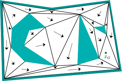
A simple example of the approach is illustrated for the case of
![]() , in which the boundary of
, in which the boundary of
![]() is polygonal.
This motion planning problem was considered in Section
6.2, but without feedback. Suppose that a
triangulation of
is polygonal.
This motion planning problem was considered in Section
6.2, but without feedback. Suppose that a
triangulation of ![]() has been computed, as described in Section
6.3.2. An example was shown in Figure
6.16. A discrete feedback plan is shown for a
particular goal state in Figure 8.10. Each
has been computed, as described in Section
6.3.2. An example was shown in Figure
6.16. A discrete feedback plan is shown for a
particular goal state in Figure 8.10. Each
![]() -cell (triangle) is labeled with an arrow that points to the next
cell.
-cell (triangle) is labeled with an arrow that points to the next
cell.
 |
For the cell that contains ![]() , a normalized version of the
inward vector field shown in Figure 8.5b can be
formed by dividing each nonzero vector by its magnitude. It can then
be translated to move its origin to
, a normalized version of the
inward vector field shown in Figure 8.5b can be
formed by dividing each nonzero vector by its magnitude. It can then
be translated to move its origin to ![]() . For each remaining
. For each remaining
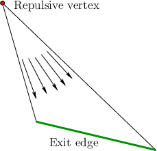
![]() -cell, a vector field must be constructed that flows into the
appropriate neighboring cell. Figure 8.11 illustrates
a simple way to achieve this. An outward vector field can be made by
negating the field shown in Figure 8.5b to obtain
-cell, a vector field must be constructed that flows into the
appropriate neighboring cell. Figure 8.11 illustrates
a simple way to achieve this. An outward vector field can be made by
negating the field shown in Figure 8.5b to obtain
![]() . This field can be normalized and translated to move the
origin to the triangle vertex that is not incident to the exit edge.
This is called the repulsive vertex in Figure
8.11. This generates a vector field that pushes all
points in the triangle to the ext edge. If the fields are constructed
in this way for each triangle, then the global vector field represents
a solution feedback plan for the problem. Integral curves (in the
sense of Filipov) lead to
. This field can be normalized and translated to move the
origin to the triangle vertex that is not incident to the exit edge.
This is called the repulsive vertex in Figure
8.11. This generates a vector field that pushes all
points in the triangle to the ext edge. If the fields are constructed
in this way for each triangle, then the global vector field represents
a solution feedback plan for the problem. Integral curves (in the
sense of Filipov) lead to ![]() in finite time.
in finite time.
 |
Steven M LaValle 2020-08-14