Next: Further Reading Up: 4.4 Closed Kinematic Chains Previous: Three links
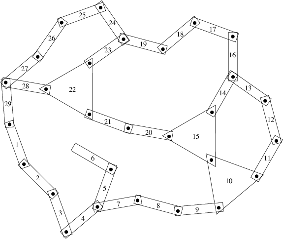
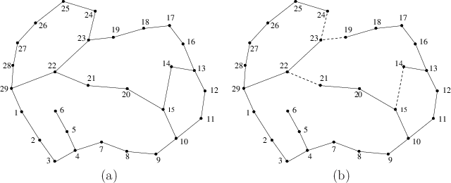
We now describe a general methodology for defining the variety. Keeping the previous examples in mind will help in understanding the formulation. In the general case, each constraint can be thought of as a statement of the form:
Theth
coordinate of a pointFor the variety in Figure 4.23b, the first coordinate of a pointneeds to be held at the value
in the body frame of
.
Suppose that ![]() links,
links,
![]() ,
,![]() ,
,
![]() , move in
, move in
![]() or
or
![]() . One link,
. One link,
![]() for convenience, is designated as the
root as defined in Section 3.4. Some links are attached
in pairs to form joints. A linkage graph,
for convenience, is designated as the
root as defined in Section 3.4. Some links are attached
in pairs to form joints. A linkage graph,
![]() , is
constructed from the links and joints. Each vertex of
, is
constructed from the links and joints. Each vertex of ![]() represents a link in
represents a link in ![]() . Each edge in
. Each edge in ![]() represents a joint.
This definition may seem somewhat backward, especially in the plane
because links often look like edges and joints look like vertices.
This alternative assignment is also possible, but it is not easy to
generalize to the case of a single link that has more than two joints.
If more than two links are attached at the same point, each generates
an edge of
represents a joint.
This definition may seem somewhat backward, especially in the plane
because links often look like edges and joints look like vertices.
This alternative assignment is also possible, but it is not easy to
generalize to the case of a single link that has more than two joints.
If more than two links are attached at the same point, each generates
an edge of ![]() .
.
 |
 |
The steps to determine the polynomial constraints that express the variety are as follows:
This is perhaps the trickiest part. For examples
like the one shown in Figure 3.27, the constraint may be
formulated as in (3.81). This is equivalent to what
was done to obtain the example in Figure 4.26, which means
that there are actually two constraints, one for each of the ![]() and
and
![]() coordinates. This will also work for the example shown in Figure
4.27 if all joints are revolute. Suppose instead that
two bodies,
coordinates. This will also work for the example shown in Figure
4.27 if all joints are revolute. Suppose instead that
two bodies,
![]() and
and
![]() , must be rigidly attached. This
requires adding one more constraint that prevents mutual rotation.
This could be achieved by selecting another point on
, must be rigidly attached. This
requires adding one more constraint that prevents mutual rotation.
This could be achieved by selecting another point on
![]() and
ensuring that one of its coordinates is in the correct position in the
body frame of
and
ensuring that one of its coordinates is in the correct position in the
body frame of
![]() . If four equations are added, two from
each point, then one of them would be redundant because there are only
three degrees of freedom possible for
. If four equations are added, two from
each point, then one of them would be redundant because there are only
three degrees of freedom possible for
![]() relative to
relative to
![]() (which
comes from the dimension of
(which
comes from the dimension of ![]() ).
).
A similar but more complicated situation occurs
for
![]() . Holding a single point fixed produces three
constraints. If a single point is held fixed, then
. Holding a single point fixed produces three
constraints. If a single point is held fixed, then
![]() may achieve
any rotation in
may achieve
any rotation in ![]() with respect to
with respect to
![]() . This implies that
. This implies that
![]() and
and
![]() are attached by a spherical joint. If they are
attached by a revolute joint, then two more constraints are needed,
which can be chosen from the coordinates of a second point. If
are attached by a spherical joint. If they are
attached by a revolute joint, then two more constraints are needed,
which can be chosen from the coordinates of a second point. If
![]() and
and
![]() are rigidly attached, then one constraint from a third
point is needed. In total, however, there can be no more than six
independent constraints because this is the dimension of
are rigidly attached, then one constraint from a third
point is needed. In total, however, there can be no more than six
independent constraints because this is the dimension of ![]() .
.
Is it possible to determine the dimension of the variety from the
number of independent constraints? The answer is generally no,
which can be easily seen from the chains of links in Section
4.4.2; they produced varieties of various dimensions,
depending on the particular equations. Techniques for computing the
dimension exist but require much more machinery than is presented here
(see the literature overview at the end of the chapter). However,
there is a way to provide a simple upper bound on the number of
degrees of freedom. Suppose the total degrees of freedom of the
linkage in spanning tree form is ![]() . Each independent constraint can
remove at most one degree of freedom. Thus, if there are
. Each independent constraint can
remove at most one degree of freedom. Thus, if there are ![]() independent constraints, then the variety can have no more than
independent constraints, then the variety can have no more than ![]() dimensions. One expression of this for a general class of
mechanisms is the Kutzbach criterion; the planar version of this
is called Grübler's formula [310].
dimensions. One expression of this for a general class of
mechanisms is the Kutzbach criterion; the planar version of this
is called Grübler's formula [310].
One final concern is the obstacle region,
![]() . Once the variety
has been identified, the obstacle region and motion planning
definitions in (4.34) and Formulation 4.1 do not
need to be changed. The configuration space
. Once the variety
has been identified, the obstacle region and motion planning
definitions in (4.34) and Formulation 4.1 do not
need to be changed. The configuration space ![]() must be redefined,
however, to be the set of configurations that satisfy the closure
constraints.
must be redefined,
however, to be the set of configurations that satisfy the closure
constraints.
Steven M LaValle 2020-08-14