Next: The 3D case Up: 3.2 Changing Position and Previous: Applying the 2D matrix Contents Index
The examples in Figure 3.5 span the main qualitative differences between various two-by-two matrices ![]() . Two of them were rotation matrices: the identity matrix, which is 0 degrees of rotation, and the
. Two of them were rotation matrices: the identity matrix, which is 0 degrees of rotation, and the ![]() -degree rotation matrix. Among the set of all possible
-degree rotation matrix. Among the set of all possible ![]() , which ones are valid rotations? We must ensure that the model does not become distorted. This is achieved by ensuring that
, which ones are valid rotations? We must ensure that the model does not become distorted. This is achieved by ensuring that ![]() satisfies the following rules:
satisfies the following rules:
To satisfy the first rule, the columns of ![]() must have unit length:
must have unit length:
To satisfy the second rule, the coordinate axes must remain perpendicular. Otherwise, shearing occurs. Since the columns of ![]() indicate how axes are transformed, the rule implies that their inner (dot) product is zero:
indicate how axes are transformed, the rule implies that their inner (dot) product is zero:
Satisfying the third rule requires that the determinant of ![]() is positive. After satisfying the first two rules, the only possible remaining determinants are
is positive. After satisfying the first two rules, the only possible remaining determinants are ![]() (the normal case) and
(the normal case) and ![]() (the mirror-image case). Thus, the rule implies that:
(the mirror-image case). Thus, the rule implies that:
 |
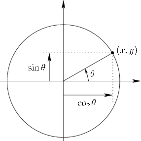
The first constraint (3.9) indicates that each column must be chosen so that its components lie on a unit circle, centered at the origin. In standard planar coordinates, we commonly write the equation of this circle as
![]() . Recall the common parameterization of the unit circle in terms of an angle
. Recall the common parameterization of the unit circle in terms of an angle ![]() that ranges from 0 to
that ranges from 0 to ![]() radians (see Figure 3.6):
radians (see Figure 3.6):
Instead of ![]() and
and ![]() , we use the notation of the matrix components. Let
, we use the notation of the matrix components. Let
![]() and
and
![]() . Substituting this into
. Substituting this into ![]() from (3.4) yields
from (3.4) yields
Think about degrees of freedom. Originally, we could chose all four components of ![]() independently, resulting in
independently, resulting in ![]() DOFs. The constraints in (3.9) each removed a DOF. Another DOF was removed by (3.10). Note that (3.11) does not reduce the DOFs; it instead eliminates exactly half of the possible transformations: The ones that are mirror flips and rotations together. The result is one DOF, which was nicely parameterized by the angle
DOFs. The constraints in (3.9) each removed a DOF. Another DOF was removed by (3.10). Note that (3.11) does not reduce the DOFs; it instead eliminates exactly half of the possible transformations: The ones that are mirror flips and rotations together. The result is one DOF, which was nicely parameterized by the angle ![]() . Furthermore, we were lucky that set of all possible 2D rotations can be nicely interpreted as points along a unit circle.
. Furthermore, we were lucky that set of all possible 2D rotations can be nicely interpreted as points along a unit circle.
Steven M LaValle 2020-11-11