
Next: Filtering Up: 9.3 Tracking Position and Previous: Camera-based implementation Contents Index
 |
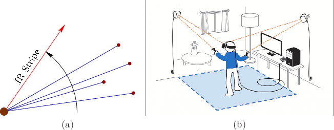 |
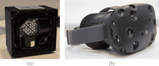
By designing a special emitter-detector pair, the visibility problem can be accurately solved over great distances. This was accomplished by the lighthouse tracking system of the 2016 HTC Vive headset, and the Minnesota scanner from 1989 [306]. Figure 9.16 shows the lighthouse tracking hardware for the HTC Vive. The operation of a camera is effectively simulated, as shown in Figure 9.17(a).
If the base station were a camera, then the sweeping vertical stripe would correspond to estimating the row of the pixel that corresponds to the feature; see Figure 9.17(a). Likewise, the sweeping horizontal stripe corresponds to the pixel column. The rotation rate of the spinning drum is known and is analogous to the camera frame rate. The precise timing is recorded as the beam hits each photodiode.
Think about polar coordinates (distance and angle) relative to the base station. Using the angular velocity of the sweep and the relative timing differences, the angle between the features as ``observed'' from the base station can be easily estimated. Although the angle between features is easily determined, their angles relative to some fixed direction from the base station must be determined. This is accomplished by an array of IR LEDs that are pulsed on simultaneously so that all photodiodes detect the flash (visible in Figure 9.16(a)). This could correspond, for example, to the instant of time at which each beam is at the 0 orientation. Based on the time from the flash until the beam hits a photodiode, and the known angular velocity, the angle of the observed feature is determined. To reduce temporal drift error, the flash may be periodically used during operation.
As in the case of the camera, the distances from the base station to the features are not known, but can be determined by solving the PnP problem. Multiple base stations can be used as well, in a way that is comparable to using multiple cameras or multiple eyes to infer depth. The result is accurate tracking over a large area, as shown in Figure 9.17(b).
Steven M LaValle 2020-11-11