Next: 7.4 Improving Latency and Up: 7. Visual Rendering Previous: VR-specific rasterization problems Contents Index
Recall from Section 4.3 that barrel and pincushion distortions are common for an optical system with a high field of view (Figure 4.20). When looking through the lens of a VR headset, a pincushion distortion typically results. If the images are drawn on the screen without any correction, then the virtual world appears to be incorrectly warped. If the user yaws his head back and forth, then fixed lines in the world, such as walls, appear to dynamically change their curvature because the distortion in the periphery is much stronger than in the center. If it is not corrected, then the perception of stationarity will fail because static objects should not appear to be warping dynamically. Furthermore, contributions may be made to VR sickness because incorrect accelerations are being visually perceived near the periphery.
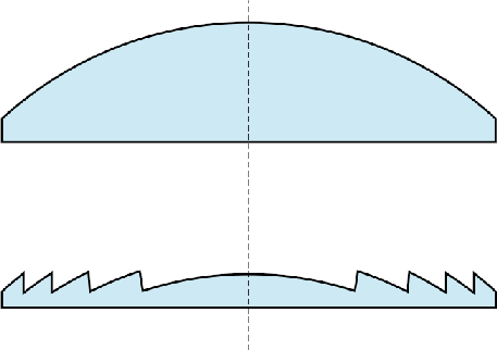 |
How can this problem be solved? Significant research is being done in this area, and the possible solutions involve different optical systems and display technologies. For example, digital light processing (DLP) technology directly projects light into the eye without using lenses. Another way to greatly reduce this problem is to use a Fresnel lens (see Figure 7.14), which more accurately controls the bending of light rays by using a corrugated or sawtooth surface over a larger area; an aspheric design can be implemented as well. A Fresnel lens is used, for example, in the HTC Vive VR headset. One unfortunate side effect of Fresnel lenses is that glaring can be frequently observed as light scatters across the ridges along the surface.
Whether small or large, the distortion can also be corrected in software. One assumption is that the distortion is circularly symmetric. This means that the amount of distortion depends only on the distance from the lens center, and not the particular direction from the center. Even if the lens distortion is perfectly circularly symmetric, it must also be placed so that it is centered over the eye. Some headsets offer IPD adjustment, which allows the distance between the lenses to be adjusted so that they are matched to the user's eyes. If the eye is not centered on the lens, then asymmetric distortion arises. The situation is not perfect because as the eye rotates, the pupil moves along a spherical arc. As the position of the pupil over the lens changes laterally, the distortion varies and becomes asymmetric. This motivates making the lens as large as possible so that this problem is reduced. Another factor is that the distortion will change as the distance between the lens and the screen is altered. This adjustment may be useful to accommodate users with nearsightedness or farsightedness, as done in the Samsung Gear VR headset. The adjustment is also common in binoculars and binoculars, which explains why many people do not need their glasses to use them. To handle distortion correctly, the headset should ideally sense the adjustment setting and take it into account.
To fix radially symmetric distortion, suppose that the transformation chain
![]() has been applied to the geometry, resulting in the canonical view volume, as covered in Section 3.5. All points that were inside of the viewing frustum now have
has been applied to the geometry, resulting in the canonical view volume, as covered in Section 3.5. All points that were inside of the viewing frustum now have ![]() and
and ![]() coordinates ranging from
coordinates ranging from ![]() to
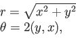
to ![]() . Consider referring to these points using polar coordinates
. Consider referring to these points using polar coordinates
![]() :
:
 |
(7.15) |
We now express the lens distortion in terms of transforming the radius ![]() , without affecting the direction
, without affecting the direction ![]() (because of symmetry). Let
(because of symmetry). Let ![]() denote a function that applies to positive real numbers and distorts the radius. Let
denote a function that applies to positive real numbers and distorts the radius. Let ![]() denote the undistorted radius, and let
denote the undistorted radius, and let ![]() denote the distorted radius. Both pincushion and barrel distortion are commonly approximated using polynomials with odd powers, resulting in
denote the distorted radius. Both pincushion and barrel distortion are commonly approximated using polynomials with odd powers, resulting in ![]() being defined as
being defined as
| (7.16) |
Correcting the distortion involves two phases:
Unfortunately, polynomial functions generally do not have inverses that can be determined or even expressed in a closed form. Therefore, approximations are used. One commonly used approximation is [119]:
 |
The transformation ![]() could be worked directly into the perspective transformation, thereby replacing
could be worked directly into the perspective transformation, thereby replacing ![]() and
and ![]() with a nonlinear operation. By leveraging the existing graphics rendering pipeline, it is instead handled as a post-processing step. The process of transforming the image is sometimes called distortion shading because it can be implemented as a shading operation in the GPU; it has nothing to do with ``shading'' as defined in Section 7.1. The rasterized image that was calculated using methods in Section 7.2 can be converted into a transformed image using (7.17), or another representation of
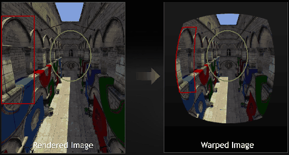
with a nonlinear operation. By leveraging the existing graphics rendering pipeline, it is instead handled as a post-processing step. The process of transforming the image is sometimes called distortion shading because it can be implemented as a shading operation in the GPU; it has nothing to do with ``shading'' as defined in Section 7.1. The rasterized image that was calculated using methods in Section 7.2 can be converted into a transformed image using (7.17), or another representation of ![]() , on a pixel-by-pixel basis. If compensating for a pincushion distortion, the resulting image will appear to have a barrel distortion; see Figure 7.15. To improve VR performance, multiresolution shading is used in Nvidia GTX 1080 GPUs. One problem is that the resolution is effectively dropped near the periphery because of the transformed image (Figure 7.15). This results in wasted shading calculations in the original image. Instead, the image can be rendered before the transformation by taking into account the final resulting resolutions after the transformation. A lower-resolution image is rendered in a region that will become compressed by the transformation.
, on a pixel-by-pixel basis. If compensating for a pincushion distortion, the resulting image will appear to have a barrel distortion; see Figure 7.15. To improve VR performance, multiresolution shading is used in Nvidia GTX 1080 GPUs. One problem is that the resolution is effectively dropped near the periphery because of the transformed image (Figure 7.15). This results in wasted shading calculations in the original image. Instead, the image can be rendered before the transformation by taking into account the final resulting resolutions after the transformation. A lower-resolution image is rendered in a region that will become compressed by the transformation.
The methods described in this section may also be used for other optical distortions that are radially symmetric. For example, chromatic aberration can be partially corrected by transforming the red, green, and blue subpixels differently. Each color is displaced radially by a different amount to compensate for the radial distortion that occurs based on its wavelength. If chromatic aberration correction is being used, then if the lenses are removed from the VR headset, it would become clear that the colors are not perfectly aligned in the images being rendered to the display. The rendering system must create a distortion of pixel placements on the basis of color so that they will be moved closer to the correct places after they pass through the lens.