Next: 15.4 Nonholonomic System Theory Up: 15.3 Optimal Paths for Previous: 15.3.2 Reeds-Shepp Curves
In recent years, two more families of optimal curves have been
determined [64,211]. Recall the
differential-drive system from Section 13.1.2, which
appears in many mobile robot systems. In many ways, it appears that
the differential drive is a special case of the simple car. The
expression of the system given in (13.17) can be made
to appear identical to the Reeds-Shepp car system in
(15.48). For example, letting ![]() and
and ![]() makes
them equivalent by assigning
makes
them equivalent by assigning
![]() and
and
![]() .
Consider the distance traveled by a point attached to the center of
the differential-drive axle using (15.42). Minimizing
this distance for any
.
Consider the distance traveled by a point attached to the center of
the differential-drive axle using (15.42). Minimizing
this distance for any ![]() and
and ![]() is trivial, as shown in
Figure 13.4 of Section 13.1.2. The center
point can be made to travel in a straight line in
is trivial, as shown in
Figure 13.4 of Section 13.1.2. The center
point can be made to travel in a straight line in
![]() . This
would be possible for the Reeds-Shepp car if
. This
would be possible for the Reeds-Shepp car if
![]() , which
implies that
, which
implies that
![]() . It therefore appeared for many
years that no interesting curves exist for the differential drive.
. It therefore appeared for many
years that no interesting curves exist for the differential drive.
The problem, however, with measuring the distance traveled by the axle
center is that pure rotations are cost-free. This occurs when the
wheels rotate at the same speed but with opposite angular velocities.
The center does not move; however, the time duration, energy
expenditure, and wheel rotations that occur are neglected. By
incorporating one or more of these into the cost functional, a
challenging optimization arises. Balkcom and Mason bounded the speed
of the differential drive and minimized the total time that it takes
to travel from ![]() to
to ![]() . Using (13.16), the
action set is defined as
. Using (13.16), the
action set is defined as
![]() , in which the
maximum rotation rate of each wheel is one (an alternative bound can
be used without loss of generality). The criterion to optimize is
, in which the
maximum rotation rate of each wheel is one (an alternative bound can
be used without loss of generality). The criterion to optimize is
 |
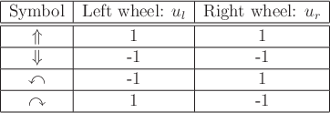
It was shown in [64] that only the four motion primitives shown in Figure 15.11 are needed to express time-optimal paths for the differential-drive robot. Each primitive corresponds to holding one action variable fixed at its limit for an interval of time. Using the symbols in Figure 15.11 (which were used in [64]), words can be formed that describe the optimal path. It has been shown that the word length is no more than five. Thus, any shortest paths may be expressed as a piecewise-constant action trajectory in which there are no more than five pieces. Every piece corresponds to one of the primitives in Figure 15.11.
 |
It is convenient in the case of the Balkcom-Mason drive to use the same symbols for both base words and for precise specification of primitives. Symmetry transformations will be applied to each base word to yield a family of eight words that precisely specify the sequences of motion primitives. Nine base words describe the shortest paths:
![\begin{figure}\scriptsize
\begin{center}
\begin{tabular}{l\vert c\vert c\vert c\...
...emath{\Downarrow}$
\\ \hline
\end{tabular} \\ [10pt]
\end{center}
\end{figure}](img6722.gif) |
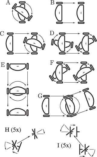
Figure 15.13 shows 40 distinct Balkcom-Mason curves
that result from applying symmetry transformations to the base words
of (15.51). There are 72 entries in Figure
15.13, but many are identical. The transformation ![]() indicates that the directions of
indicates that the directions of
![]() and
and
![]() are flipped from the
base word. The transformation
are flipped from the
base word. The transformation ![]() reverses the order of the motion
primitives. The transformation
reverses the order of the motion
primitives. The transformation ![]() flips the directions of
flips the directions of
![]() and
and
![]() . The transformations commute, and there are seven possible
ways to combine them, which contributes to a row of Figure
15.13.
. The transformations commute, and there are seven possible
ways to combine them, which contributes to a row of Figure
15.13.
 |
To construct an LPM or distance function,
the same issues arise as for the Reeds-Shepp and Dubins cars. Rather
than testing all ![]() words to find the shortest path, simple tests
can be defined over which a particular word becomes active
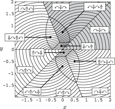
[64]. A slice of the precise cell decomposition and the
resulting optimal cost-to-go (which can be called the
Balkcom-Mason metric) are shown in Figure 15.14.
words to find the shortest path, simple tests
can be defined over which a particular word becomes active
[64]. A slice of the precise cell decomposition and the
resulting optimal cost-to-go (which can be called the
Balkcom-Mason metric) are shown in Figure 15.14.
Steven M LaValle 2020-08-14