Next: 13.1.2.3 A simple unicycle Up: 13.1.2 Kinematics for Wheeled Previous: 13.1.2.1 A simple car
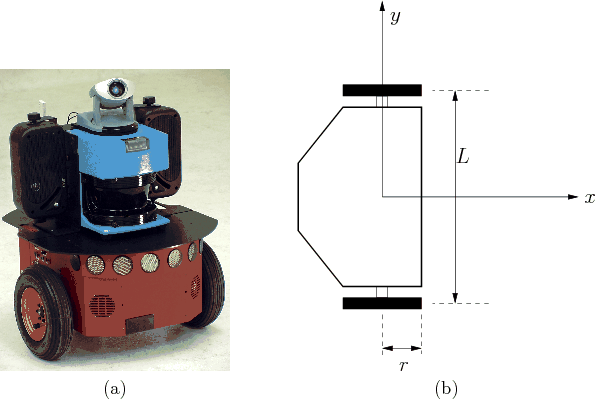
Most indoor mobile robots do not move like a car. For example, consider the mobile robotics platform shown in Figure 13.2a. This is an example of the most popular way to drive indoor mobile robots. There are two main wheels, each of which is attached to its own motor. A third wheel (not visible in Figure 13.2a) is placed in the rear to passively roll along while preventing the robot from falling over.
 |
 |
To construct a simple model of the constraints that arise from the
differential drive, only the distance ![]() between the two wheels,
and the wheel radius,
between the two wheels,
and the wheel radius, ![]() , are necessary. See Figure
13.2b. The action vector
, are necessary. See Figure
13.2b. The action vector
![]() directly
specifies the two angular wheel velocities (e.g., in radians per
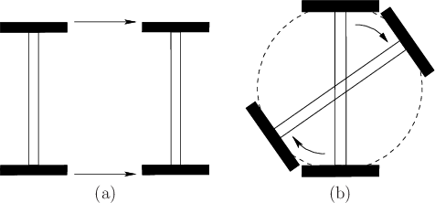
second). Consider how the robot moves as different actions are
applied. See Figure 13.3. If
directly
specifies the two angular wheel velocities (e.g., in radians per
second). Consider how the robot moves as different actions are
applied. See Figure 13.3. If
![]() , then
the robot moves forward in the direction that the wheels are pointing.
The speed is proportional to
, then
the robot moves forward in the direction that the wheels are pointing.
The speed is proportional to ![]() . In general, if
. In general, if ![]() , then
the distance traveled over a duration
, then
the distance traveled over a duration ![]() of time is
of time is ![]() (because
(because ![]() is the total angular displacement of the wheels). If
is the total angular displacement of the wheels). If
![]() , then the robot rotates clockwise because the
wheels are turning in opposite directions. This motivates the
placement of the body-frame origin at the center of the axle between
the wheels. By this assignment, no translation occurs if the wheels
rotate at the same rate but in opposite directions.
, then the robot rotates clockwise because the
wheels are turning in opposite directions. This motivates the
placement of the body-frame origin at the center of the axle between
the wheels. By this assignment, no translation occurs if the wheels
rotate at the same rate but in opposite directions.
Based on these observations, the configuration transition equation is
It is sometimes preferable to transform the action space. Let
![]() and
and
![]() . In this case,
. In this case,
![]() can be interpreted as an action variable that means
``translate,'' and
can be interpreted as an action variable that means
``translate,'' and ![]() means ``rotate.'' Using these actions,
the configuration transition equation becomes
means ``rotate.'' Using these actions,
the configuration transition equation becomes
 |
Recall the question asked about shortest paths for the Reeds-Shepp and
Dubins cars. The same question for the differential drive turns out
to be uninteresting because the differential drive can cause the
center of its axle to follow any continuous path in
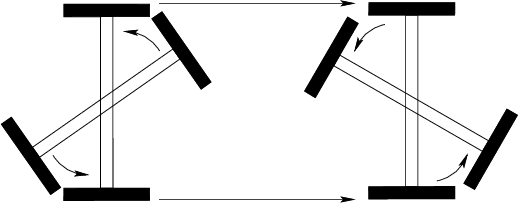
![]() . As
depicted in Figure 13.4, it can move between any two
configurations by: 1) first rotating itself to point the wheels to the
goal position, which causes no translation; 2) translating itself to
the goal position; and 3) rotating itself to the desired orientation,
which again causes no translation. The total distance traveled by the
center of the axle is always the Euclidean distance in
. As
depicted in Figure 13.4, it can move between any two
configurations by: 1) first rotating itself to point the wheels to the
goal position, which causes no translation; 2) translating itself to
the goal position; and 3) rotating itself to the desired orientation,
which again causes no translation. The total distance traveled by the
center of the axle is always the Euclidean distance in
![]() between
the two desired positions.
between
the two desired positions.
This may seem like a strange effect due to the placement of the
coordinate origin. Rotations seem to have no cost. This can be fixed
by optimizing the total amount of wheel rotation or time required, if
the speed is held fixed [64]. Suppose that
![]() . Determining the minimum time required to travel between
two configurations is quite interesting and is covered in Section
15.3. This properly takes into account the cost of
rotating the robot, even if it does not cause a translation.
. Determining the minimum time required to travel between
two configurations is quite interesting and is covered in Section
15.3. This properly takes into account the cost of
rotating the robot, even if it does not cause a translation.
Steven M LaValle 2020-08-14