Next: 14.4.1.2 Extensions and other Up: 14.4.1 Searching on a Previous: 14.4.1 Searching on a
First consider the double integrator from Example 13.3.
Let
![]() and
and
![]() . This models the motion of
a free-floating particle in
. This models the motion of
a free-floating particle in
![]() , as described in Section
13.3.2. The phase space is
, as described in Section
13.3.2. The phase space is
![]() , and
, and
![]() . Let
. Let
![]() . The coming ideas can be easily
generalized to allow any acceleration bound
. The coming ideas can be easily
generalized to allow any acceleration bound
![]() by letting
by letting
![]() ; however,
; however,
![]() will be chosen to
simplify the presentation.
will be chosen to
simplify the presentation.
The differential equation
![]() can be integrated once to yield
can be integrated once to yield
 |
 |
A discrete-time model exists for which the reachability graph is
trapped on a lattice. This is obtained by letting
![]() and
and ![]() be any positive real number. The vector fields over
be any positive real number. The vector fields over
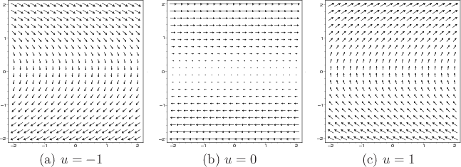
![]() that correspond to the cases of
that correspond to the cases of ![]() ,
, ![]() , and
, and ![]() are shown
in Figure 14.12. Switching between these fields at every
are shown
in Figure 14.12. Switching between these fields at every
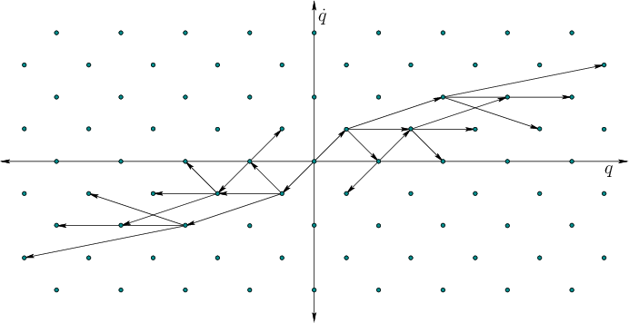
![]() and integrating yields the reachability graph shown in
Figure 14.13.
and integrating yields the reachability graph shown in
Figure 14.13.
This leads to a discrete-time transition equation of the form
![]() , in which
, in which
![]() , and
, and ![]() represents time
represents time
![]() . Any action trajectory can be specified as an action
sequence; for example a six-stage action sequence may be given by
. Any action trajectory can be specified as an action
sequence; for example a six-stage action sequence may be given by
![]() . Start from
. Start from
![]() . At any
stage
. At any
stage ![]() and for any action sequence, the resulting state
and for any action sequence, the resulting state
![]() can be expressed as
can be expressed as
 |
(14.23) |
The neighborhood structure is not the same as those in Section
5.4.2 because of drift. For ![]() , imagine having a
stack of horizontal conveyor belts that carry points to the right if
they are above the
, imagine having a
stack of horizontal conveyor belts that carry points to the right if
they are above the ![]() -axis, and to the left if they are below it (see
Figure 14.12b). The speed of the conveyor belt is given
by
-axis, and to the left if they are below it (see
Figure 14.12b). The speed of the conveyor belt is given
by ![]() . If
. If ![]() , the distance traveled along
, the distance traveled along ![]() is
is
![]() . This causes horizontal motion to the right in the phase
plane if
. This causes horizontal motion to the right in the phase
plane if
![]() and horizontal motion to the left if
and horizontal motion to the left if
![]() . Observe in Figure 14.13 that larger motions result as
. Observe in Figure 14.13 that larger motions result as
![]() increases. If
increases. If
![]() , then no horizontal motion can
occur. If
, then no horizontal motion can
occur. If
![]() , then the
, then the ![]() coordinate changes by
coordinate changes by
![]() . This slowing down or speeding up also
affects the position along
. This slowing down or speeding up also
affects the position along ![]() .
.
For most realistic problems, there is an upper bound on speed. Let
![]() be a positive constant and assume that
be a positive constant and assume that
![]() . Furthermore, assume that
. Furthermore, assume that ![]() is bounded (all values of
is bounded (all values of
![]() are contained in an interval of
are contained in an interval of
![]() ). Since the
reachability graph is a lattice and the states are now confined to a
bounded subset of
). Since the
reachability graph is a lattice and the states are now confined to a
bounded subset of
![]() , the number of vertices in the reachability
graph is finite. For any fixed
, the number of vertices in the reachability
graph is finite. For any fixed ![]() , the lattice can be
searched using any of the algorithms of Section 2.2. The
search starts on a reachability graph for which the initial vertex is
, the lattice can be
searched using any of the algorithms of Section 2.2. The
search starts on a reachability graph for which the initial vertex is
![]() . Trajectories that are approximately time-optimal can be
obtained by using breadth-first search (Dijkstra's algorithm
could alternatively be used, but it is more expensive). Resolution
completeness can be obtained by reducing
. Trajectories that are approximately time-optimal can be
obtained by using breadth-first search (Dijkstra's algorithm
could alternatively be used, but it is more expensive). Resolution
completeness can be obtained by reducing ![]() by a constant
factor each time the search fails to find a solution. As mentioned in
Section 5.4.2, it is not required to construct an entire
grid resolution at once. Samples can be gradually added, and the
connectivity can be updated efficiently using the union-find algorithm
[243,823]. A rigorous approximation algorithm
framework will be presented shortly, which indicates how close the
solution is to optimal, expressed in terms of input parameters to the
algorithm.
by a constant
factor each time the search fails to find a solution. As mentioned in
Section 5.4.2, it is not required to construct an entire
grid resolution at once. Samples can be gradually added, and the
connectivity can be updated efficiently using the union-find algorithm
[243,823]. A rigorous approximation algorithm
framework will be presented shortly, which indicates how close the
solution is to optimal, expressed in terms of input parameters to the
algorithm.
 |
Recall the problem of connecting to grid points, which was illustrated
in Figure 5.14b. If the goal region ![]() contains lattice points, then exact arrival at the goal occurs. If it
does not contain lattice points, as in the common case of
contains lattice points, then exact arrival at the goal occurs. If it
does not contain lattice points, as in the common case of ![]() being a single point, then some additional work is needed to connect a
goal state to a nearby lattice point. This actually corresponds to a
BVP, but it is easy to solve
for the double integrator. The set of states that can be reached from
some state
being a single point, then some additional work is needed to connect a
goal state to a nearby lattice point. This actually corresponds to a
BVP, but it is easy to solve
for the double integrator. The set of states that can be reached from
some state ![]() within time
within time ![]() lie within a cone, as
shown in Figure 14.14a. Lattice points that fall into
the cone can be easily connected to
lie within a cone, as
shown in Figure 14.14a. Lattice points that fall into
the cone can be easily connected to ![]() by applying a constant
action in
by applying a constant
action in ![]() . Likewise,
. Likewise, ![]() does not even have to coincide with
a lattice point. Thus, it is straightforward to connect
does not even have to coincide with
a lattice point. Thus, it is straightforward to connect ![]() to a
lattice point, obtain a trajectory that arrives at a lattice point
near
to a
lattice point, obtain a trajectory that arrives at a lattice point
near ![]() , and then connect it exactly to
, and then connect it exactly to ![]() .
.
Steven M LaValle 2020-08-14