
Next: Critical gap events Up: 12.3 Environment Uncertainty and Previous: Competitive ratios
This section presents gap navigation trees (GNTs) [943,945], which are a data structure and associated planning algorithm for performing optimal navigation in the continuous environments that were considered in Section 12.3.3. It is assumed in this section that the robot is equipped with a gap sensor, as depicted in Figure 11.16 of Section 11.5.1. At every instant in time, the robot has available one action for each gap that is visible in the gap sensor. If an action is applied, then the robot moves toward the corresponding gap. This can be applied over continuous time, which enables the robot to ``chase'' a particular gap. The robot has no other sensing information: It has no compass and no ability to measure distances. Therefore, it is impossible to construct a map of the environment that contains metric information.
Assume that the robot is placed into an unknown but simply connected
planar environment, ![]() . The GNT can be extended to the case of
multiply connected environments; however, in this case there are
subtle issues with distinguishability, and it is only possible to
guarantee optimality within a homotopy class of paths
[944]. By analyzing the way that critical events occur
in the gap sensor, a tree representation can be built that indicates
how to move optimally in the environment, even though precise
measurements cannot be taken. Since a gap sensor cannot even measure
distances, it may seem unusual that the robot can move along shortest
paths without receiving any distance (or metric) information. This
will once again illustrate the power of I-spaces.
. The GNT can be extended to the case of
multiply connected environments; however, in this case there are
subtle issues with distinguishability, and it is only possible to
guarantee optimality within a homotopy class of paths
[944]. By analyzing the way that critical events occur
in the gap sensor, a tree representation can be built that indicates
how to move optimally in the environment, even though precise
measurements cannot be taken. Since a gap sensor cannot even measure
distances, it may seem unusual that the robot can move along shortest
paths without receiving any distance (or metric) information. This
will once again illustrate the power of I-spaces.
The appearance of the environment relative to the position of the robot is encoded as a tree that indicates how the gaps change as the robot moves. It provides the robot with sufficient information to move to any part of the environment while traveling along the shortest path. It is important to understand that the tree does not correspond to some static map of the environment. It expresses how the environment appears relative to the robot and may therefore change as the robot moves in the environment.
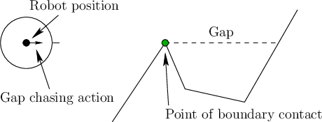 |
The root of the tree represents the gap sensor. For each gap that
currently appears in the sensor, an edge is connected to the root.
Let these edges be called root edges. Each root edge
corresponds to an action that can be applied by the robot. By
selecting a root edge, the action moves the robot along a straight
line toward that gap. Thus, there is a simple control model that
enables the robot to move precisely toward a particular point along
the boundary,
![]() , as shown in Figure 12.27.
, as shown in Figure 12.27.
Let ![]() be the visibility region, which is the set of all
points in
be the visibility region, which is the set of all
points in ![]() that are visible from
that are visible from ![]() . Let
. Let
![]() be
called the shadow region, which is the set of all points not visible from
be
called the shadow region, which is the set of all points not visible from ![]() . Let each connected component of the shadow
region be called a shadow component. Every gap in the gap
sensor corresponds to a line segment in
. Let each connected component of the shadow
region be called a shadow component. Every gap in the gap
sensor corresponds to a line segment in ![]() that touches
that touches
![]() in two places (for example, see Figure 11.15a). Each of
these segments forms a boundary between the visibility region and a
shadow component. If the robot would like to travel to this shadow
component, the shortest way is to move directly to the gap. When moving
toward a gap, the robot eventually reaches
in two places (for example, see Figure 11.15a). Each of
these segments forms a boundary between the visibility region and a
shadow component. If the robot would like to travel to this shadow
component, the shortest way is to move directly to the gap. When moving
toward a gap, the robot eventually reaches
![]() , at which
point a new action must be selected.
, at which
point a new action must be selected.