Next: 2.2 Software Up: 2.1 Hardware Previous: Sensors Contents Index
 |
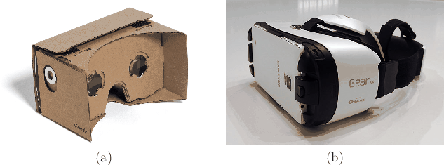
A computer executes the virtual world generator (VWG). Where should this computer be? Although unimportant for world-fixed displays, the location is crucial for body-fixed displays. If a separate PC is needed to power the system, then fast, reliable communication must be provided between the headset and the PC. This connection is currently made by wires, leading to an awkward tether; current wireless speeds are not sufficient. As you have noticed, most of the needed sensors exist on a smartphone, as well as a moderately powerful computer. Therefore, a smartphone can be dropped into a case with lenses to provide a VR experience with little added costs (Figure 2.11). The limitation, though, is that the VWG must be simpler than in the case of a separate PC so that it runs on less-powerful computing hardware. In the near future, we expect to see wireless, all-in-one headsets that contain all of the essential parts of smartphones for delivering VR experiences. These will eliminate unnecessary components of smartphones (such as the additional case), and will instead have customized optics, microchips, and sensors for VR.
In addition to the main computing systems, specialized computing hardware may be utilized. Graphical processing units (GPUs) have been optimized for quickly rendering graphics to a screen and they are currently being adapted to handle the specific performance demands of VR. Also, a display interface chip converts an input video into display commands. Finally, microcontrollers are frequently used to gather information from sensing devices and send them to the main computer using standard protocols, such as USB.
To conclude with hardware, Figure 2.12 shows the hardware components for the Oculus Rift DK2, which became available in late 2014. In the lower left corner, you can see a smartphone screen that serves as the display. Above that is a circuit board that contains the IMU, display interface chip, a USB driver chip, a set of chips for driving LEDs on the headset for tracking, and a programmable microcontroller. The lenses, shown in the lower right, are placed so that the smartphone screen appears to be ``infinitely far'' away, but nevertheless fills most of the field of view of the user. The upper right shows flexible circuits that deliver power to IR LEDs embedded in the headset (they are hidden behind IR-transparent plastic). A camera is used for tracking, and its parts are shown in the center.
Steven M LaValle 2020-11-11