Next: Yaw correction Up: 9.2 Tracking 3D Orientation Previous: Registration Contents Index
The drift error ![]() in (9.3) was a single angle, which could be positive or negative. If added to the estimate
in (9.3) was a single angle, which could be positive or negative. If added to the estimate
![]() , the true orientation
, the true orientation ![]() would be obtained. It is similar for the 3D case, but with quaternion algebra. The 3D drift error is expressed as
would be obtained. It is similar for the 3D case, but with quaternion algebra. The 3D drift error is expressed as
Since the drift error is a 3D rotation, it could be constructed as the product of a yaw, pitch, and a roll. Let tilt error refer to the part of the drift error that corresponds to pitch and roll. This will be detected using an ``up'' sensor. Let yaw error refer to the remaining part of the drift error, which will be detecting using a ``compass''. In reality, there do not exist perfect ``up'' and ``compass'' sensors, which will be addressed later.
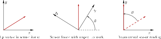 |
Suppose that a sensor attached to the rigid body always reports an ``up'' vector that is parallel to ![]() axis in the fixed, world coordinate frame. In other words, it would be parallel to gravity. Since the sensor is mounted to the body, it reports its values in the coordinate frame of the body. For example, if the body were rolled
axis in the fixed, world coordinate frame. In other words, it would be parallel to gravity. Since the sensor is mounted to the body, it reports its values in the coordinate frame of the body. For example, if the body were rolled ![]() degrees so that its
degrees so that its ![]() axis is pointing straight up, then the ``up'' vector would be reported as
axis is pointing straight up, then the ``up'' vector would be reported as ![]() , instead of
, instead of ![]() . To fix this, it would be convenient to transform the sensor output into the world frame. This involves rotating it by
. To fix this, it would be convenient to transform the sensor output into the world frame. This involves rotating it by ![]() , the body orientation. For our example, this roll rotation would transform
, the body orientation. For our example, this roll rotation would transform ![]() into
into ![]() . Figure 9.3 shows a 2D example.
. Figure 9.3 shows a 2D example.
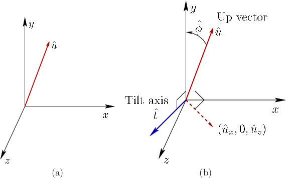
Now suppose that drift error has occurred and that
![]() is the estimated orientation. If this transform is applied to the ``up'' vector, then because of drift error, it might not be aligned with the
is the estimated orientation. If this transform is applied to the ``up'' vector, then because of drift error, it might not be aligned with the ![]() axis, as shown Figure 9.4. The up vector
axis, as shown Figure 9.4. The up vector ![]() is projected into the
is projected into the ![]() plane to obtain
plane to obtain
![]() . The tilt axis lies in the
. The tilt axis lies in the ![]() plane and is constructed as the normal to the projected up vector:
plane and is constructed as the normal to the projected up vector:
![]() . Performing a rotation of
. Performing a rotation of ![]() about the axis
about the axis ![]() would move the up vector into alignment with the
would move the up vector into alignment with the ![]() axis. Thus, the tilt error portion of the drift error is the quaternion
axis. Thus, the tilt error portion of the drift error is the quaternion
![]() .
.
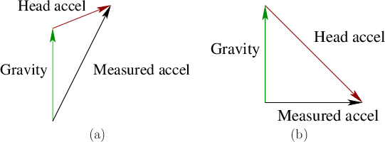
Unfortunately, there is no sensor that directly measures ``up''. In practice, the accelerometer is used to measure the ``up'' direction because gravity acts on the sensor, causing the sensation of upward acceleration at roughly ![]() m/
m/![]() . The problem is that it also responds to true linear acceleration of the rigid body, and this cannot be separated from gravity due to the Einstein equivalence principle. It measures the vector sum of gravity and true linear acceleration, as shown in Figure 9.5. A simple heuristic is to trust accelerometer outputs as an estimate of the ``up'' direction only if its magnitude is close to
. The problem is that it also responds to true linear acceleration of the rigid body, and this cannot be separated from gravity due to the Einstein equivalence principle. It measures the vector sum of gravity and true linear acceleration, as shown in Figure 9.5. A simple heuristic is to trust accelerometer outputs as an estimate of the ``up'' direction only if its magnitude is close to ![]() m
m![]() [76]. This could correspond to the common case in which the rigid body is stationary. However, this assumption is unreliable because downward and lateral linear accelerations can be combined to provide an output magnitude that is close to
[76]. This could correspond to the common case in which the rigid body is stationary. However, this assumption is unreliable because downward and lateral linear accelerations can be combined to provide an output magnitude that is close to ![]() m
m![]() , but with a direction that is far from ``up''. Better heuristics may be built from simultaneously considering the outputs of other sensors or the rate at which ``up'' appears to change.
, but with a direction that is far from ``up''. Better heuristics may be built from simultaneously considering the outputs of other sensors or the rate at which ``up'' appears to change.
Assuming that the accelerometer is producing a reliable estimate of the gravity direction, the up vector ![]() is calculated from the accelerometer output
is calculated from the accelerometer output ![]() by using (3.34), to obtain
by using (3.34), to obtain
Steven M LaValle 2020-11-11