Next: The power of prediction Up: 7.4 Improving Latency and Previous: Improving rendering performance Contents Index
The problem of waiting for coherent VWG frames also arises in the process of rendering frames to the display: When it is time to scan out the rendered image to the display, it might not be finished yet. Recall from Section 5.4 that most displays have a rolling scanout that draws the rows of the rasterized image, which sits in the video memory, onto the screen one-by-one. This was motivated by the motion of the electron beam that lit phosphors on analog TV screens. The motion is left to right, and top to bottom, much in the same way we would write out a page of English text with a pencil and paper. Due to inductive inertia in the magnetic coils that bent the beam, there was a period of several milliseconds called VBLANK (vertical blanking interval) in which the beam moves from the lower right back to the upper left of the screen to start the next frame. During this time, the beam was turned off to avoid drawing a diagonal streak across the frame, hence, the name ``blanking''. Short blanking intervals also occurred as each horizontal line to bring the beam back from the right to the left.
In the era of digital displays, the scanning process in unnecessary, but it nevertheless persists and causes some trouble. Suppose that a display runs at ![]() FPS. In this case, a request to draw a new rendered image is made every
FPS. In this case, a request to draw a new rendered image is made every ![]() ms. Suppose that VBLANK occurs for
ms. Suppose that VBLANK occurs for ![]() ms and the remaining
ms and the remaining ![]() ms is spent drawing lines on the display. If the new rasterized image is written to the video memory during the
ms is spent drawing lines on the display. If the new rasterized image is written to the video memory during the ![]() ms of VBLANK, then it will be correctly drawn in the remaining
ms of VBLANK, then it will be correctly drawn in the remaining ![]() ms. It is also possible to earn extra time through beam racing [25,216]. However, if a new image is being written and passes where the beam is scanning it out, then tearing occurs because it appears as if is screen is torn into pieces; see Figure 7.17. If the VWG and rendering system produce frames at
ms. It is also possible to earn extra time through beam racing [25,216]. However, if a new image is being written and passes where the beam is scanning it out, then tearing occurs because it appears as if is screen is torn into pieces; see Figure 7.17. If the VWG and rendering system produce frames at ![]() FPS, then parts of 3 or 4 images could appear on the display because the image changes several times while the lines are being scanned out. One solution to this problem to use VSYNC (pronounced ``vee sink''), which is a flag that prevents the video memory from being written outside of the VBLANK interval.
FPS, then parts of 3 or 4 images could appear on the display because the image changes several times while the lines are being scanned out. One solution to this problem to use VSYNC (pronounced ``vee sink''), which is a flag that prevents the video memory from being written outside of the VBLANK interval.
 |
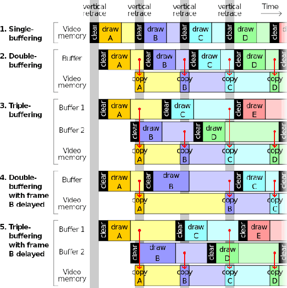
Another strategy to avoid tearing is buffering, which is shown in Figure 7.18. The approach is simple for programmers because it allows the frames to be written in memory that is not being scanned for output to the display. The unfortunate side effect is that it increases the latency. For double buffering, a new frame is first drawn into the buffer and then transferred to the video memory during VBLANK. It is often difficult to control the rate at which frames are produced because the operating system may temporarily interrupt the process or alter its priority. In this case, triple buffering is an improvement that allows more time to render each frame. For avoiding tearing and providing smooth video game performance, buffering has been useful; however, it is detrimental to VR because of the increased latency.
Ideally, the displays should have a global scanout, in which all pixels are switched at the same time. This allows a much longer interval to write to the video memory and avoids tearing. It would also reduce the latency in the time it takes to scan the first pixel to the last pixel. In our example, this was an ![]() ms interval. Finally, displays should reduce the pixel switching time as much as possible. In a smartphone LCD screen, it could take up to
ms interval. Finally, displays should reduce the pixel switching time as much as possible. In a smartphone LCD screen, it could take up to ![]() ms to switch pixels; however, OLED pixels can be switched in under
ms to switch pixels; however, OLED pixels can be switched in under ![]() ms.
ms.
Steven M LaValle 2020-11-11