Next: 2.2 Searching for Feasible Up: 2.1 Introduction to Discrete Previous: 2.1.1 Problem Formulation
 |
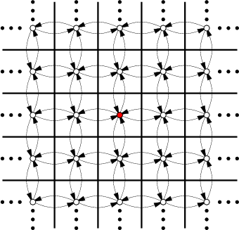
This will be expressed using Formulation 2.1. Let ![]() be
the set of all integer pairs of the form
be
the set of all integer pairs of the form ![]() , in which
, in which
![]() (
(
![]() denotes the set of all integers). Let
denotes the set of all integers). Let
![]() . Let
. Let ![]() for all
for all ![]() .
The state transition equation is
.
The state transition equation is
![]() , in which
, in which ![]() and
and ![]() are treated as two-dimensional vectors for the purpose
of addition. For example, if
are treated as two-dimensional vectors for the purpose
of addition. For example, if ![]() and
and ![]() , then
, then
![]() . Suppose for convenience that the initial state is
. Suppose for convenience that the initial state is
![]() . Many interesting goal sets are possible. Suppose,
for example, that
. Many interesting goal sets are possible. Suppose,
for example, that
![]() . It is easy to find a
sequence of actions that transforms the state from
. It is easy to find a
sequence of actions that transforms the state from ![]() to
to
![]() .
.
 |
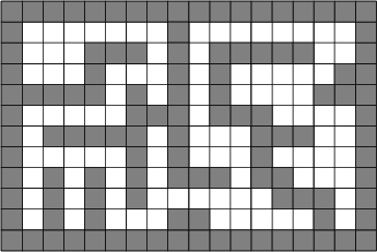
The problem can be made more interesting by shading in some of the
square tiles to represent obstacles that the robot must avoid, as
shown in Figure 2.2. In this case, any tile that is
shaded has its corresponding vertex and associated edges deleted from
the state transition graph. An outer boundary can be made to fence in
a bounded region so that ![]() becomes finite. Very complicated
labyrinths can be constructed.
becomes finite. Very complicated
labyrinths can be constructed.
![]()
It is important to note that a planning problem is usually specified
without explicitly representing the entire state transition graph.
Instead, it is revealed incrementally in the planning process. In
Example 2.1, very little information actually needs to
be given to specify a graph that is infinite in size. If a planning
problem is given as input to an algorithm, close attention must be
paid to the encoding when performing a complexity analysis. For a
problem in which ![]() is infinite, the input length must still be
finite. For some interesting classes of problems it may be possible
to compactly specify a model that is equivalent to Formulation
2.1. Such representation issues have been the basis of much
research in artificial intelligence over the past decades as different
representation logics have been proposed; see Section 2.4
and [382]. In a sense, these representations can be
viewed as input compression schemes.
is infinite, the input length must still be
finite. For some interesting classes of problems it may be possible
to compactly specify a model that is equivalent to Formulation
2.1. Such representation issues have been the basis of much
research in artificial intelligence over the past decades as different
representation logics have been proposed; see Section 2.4
and [382]. In a sense, these representations can be
viewed as input compression schemes.
Readers experienced in computer engineering might recognize that when
![]() is finite, Formulation 2.1 appears almost identical to
the definition of a finite state machine or Mealy/Moore
machines. Relating the two models, the actions can be interpreted as
inputs to the state machine, and the output of the machine
simply reports its state. Therefore, the feasible planning problem
(if
is finite, Formulation 2.1 appears almost identical to
the definition of a finite state machine or Mealy/Moore
machines. Relating the two models, the actions can be interpreted as
inputs to the state machine, and the output of the machine
simply reports its state. Therefore, the feasible planning problem
(if ![]() is finite) may be interpreted as determining whether there
exists a sequence of inputs that makes a finite state machine
eventually report a desired output. From a planning perspective, it
is assumed that the planning algorithm has a complete specification of
the machine transitions and is able to read its current state at any
time.
is finite) may be interpreted as determining whether there
exists a sequence of inputs that makes a finite state machine
eventually report a desired output. From a planning perspective, it
is assumed that the planning algorithm has a complete specification of
the machine transitions and is able to read its current state at any
time.
Readers experienced with theoretical computer science may observe
similar connections to a deterministic finite automaton (DFA),
which is a special kind of finite state machine that reads an input string and makes a decision about whether to accept or
reject the string. The input string is just a finite sequence
of inputs, in the same sense as for a finite state machine. A DFA
definition includes a set of accept states, which in the
planning context can be renamed to the goal set. This makes the
feasible planning problem (if ![]() is finite) equivalent to determining
whether there exists an input string that is accepted by a given DFA.
Usually, a language is associated with a DFA, which is the set of all
strings it accepts. DFAs are important in the theory of computation
because their languages correspond precisely to regular expressions.
The planning problem amounts to determining whether the empty language
is associated with the DFA.
is finite) equivalent to determining
whether there exists an input string that is accepted by a given DFA.
Usually, a language is associated with a DFA, which is the set of all
strings it accepts. DFAs are important in the theory of computation
because their languages correspond precisely to regular expressions.
The planning problem amounts to determining whether the empty language
is associated with the DFA.
Thus, there are several ways to represent and interpret the discrete feasible planning problem that sometimes lead to a very compact, implicit encoding of the problem. This issue will be revisited in Section 2.4. Until then, basic planning algorithms are introduced in Section 2.2, and discrete optimal planning is covered in Section 2.3.
Steven M LaValle 2020-08-14