Next: Constraining parameters Up: 3.4 Transforming Kinematic Trees Previous: Common joints for
Now consider modeling a more complicated collection of attached links.
The main novelty is that one link may have joints attached to it
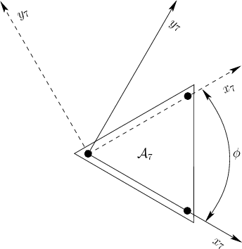
in more than two locations, as in
![]() in Figure
3.22. A link with more than two joints will be
referred to as a junction.
in Figure
3.22. A link with more than two joints will be
referred to as a junction.
If there is only one junction, then most of the complications arising from junctions can be avoided by choosing the junction as the root. For example, for a simple humanoid model, the torso would be a junction. It would be sensible to make this the root of the tree, as opposed to the right foot. The legs, arms, and head could all be modeled as independent chains. In each chain, the only concern is that the first link of each chain does not attach to the same point on the torso. This can be solved by inserting a fixed, fictitious link that connects from the origin of the torso to the attachment point of the limb.
 |
The situation is more interesting if there are multiple junctions.
Suppose that Figure 3.22 represents part of a 2D system
of links for which the root,
![]() , is attached via a chain of
links to
, is attached via a chain of
links to
![]() . To transform link
. To transform link
![]() , the tools from Section
3.3.1 may be directly applied to yield a sequence of
transformations,
, the tools from Section
3.3.1 may be directly applied to yield a sequence of
transformations,
Steven M LaValle 2020-08-14